Ultrasonic Weld Seam Testing
Weld testing is one of the main application fields of ultrasonic testing. Using ultrasonic flaw detectors, NDT technicians find and characterize discontinuities within the weld that might lead to material or component failure. Ultrasonic weld testing is part of weld quality control and is crucial for ensuring safety in a wide range of industries: for example, it can be instrumental in preventing plane crashes, reactor failures, and oil platform explosions.
Capabilities, Challenges, and Limitations
Ultrasonic weld inspection is a complex process that requires qualified inspectors. Many factors have to be considered before a test can be carried out, including:
- Physics of ultrasound - Waves modes, propagation, attenuation, reflection, mode conversions, etc.
- Transducer operation, theory and characteristics - Piezoelectric effect, radiated field, beam spread, energy loss, etc.
- Equipment operation - Pulser, receiver, data presentation, etc.
- Ultrasonic testing methods - Pulse-Echo, Through Transmission, Pitch-Catch, etc.
- Application specific requirements - Weld type, shape, dimensions, surface quality, etc.
- Equipment calibration and evaluation methods - DAC, DGS, AWS, etc.
Advantages
- High sensitivity to surface and subsurface discontinuities
- Superior penetration depth compared to othe NDT methods
- When using the pulse echo technique, the test object can be accessed only from one side
- High accuracy in determining the position of the discontinuity and estimating its size and shape
- Minimal part preparation
- Digital equipment provides immediate results
- Thickness measurement can be performed in addition to flaw detection
Limitations
- The surface and geometry of the test specimen must allow the propagation of ultrasound through the material
- A coupling medium is required to allow the transfer of sound energy into the test object
- Materials that are rough, irregular in shape, very small, exceptionally thin, or not homogeneous are difficult to inspect
- Lack of sensitivity to linear defects oriented parallel to the sound beam propagation
- Reference standards are required for equipment calibration and the characterization of discontinuities
Defining the ultrasonic testing task
There is no doubt that ultrasonic weld inspection is not an easy task. To better understand this, let’s take a closer look at the procedure itself:
- What kind of welds are going to be inspected? (Butt joint, corner joint, lap joint, etc.)
- What is the object and where are the welds located? (Pressure vessel, pipeline, and other construction)
- What are we going to look for? (To detect and evaluate all discontinuities which need to be registered according to a quality level chosen for the task).
- A sketch must be made, on which the locations of the welds are marked. In addition, the main dimensions, material thickness and type must be stated.
- In which production phase should the test be carried out? (Usually it is performed after the welding and heat treatment process and after a visual and magnetic particle inspection has qualified the object for further inspection)
- What is the inspection coverage? How many welds are to be inspected? (It is not always necessary to test 100% of the welds. Often weak spots are defined where the inspection has to be carried out.)
- Is the entire volume of the weld to be inspected? (Usually the testing is also expanded to cover heat affected zones. With this in mind, the maximum offset of the angle beam probe from the centre of the weld can be calculated.)
- Once the maximum offset is defined, the probe movement zone has to be tested for inclusion or delamination (using a dual element probe) which may negatively influence the angle beam inspection. Sometimes this step can be skipped if the welded components (plates, pipes, etc.) have a test certificate from the manufacturer.
- Which quality class are we testing against? (This has the biggest impact on the evaluation of indications in the weld. The higher the quality class, the smaller the defects which must be registered and evaluated.)
- Which evaluation method is used? (There are three basic evaluation methods used in industry: DGS, DAC and AWS.)
Welding Defects
There are different types of discontinuities and the most typical welding defects are:
- Point indications
- Large indications
- Longitudinal indications
- Transverse indications
- The evaluation method and reference level for each type of probe used in the test must be defined. This selection is closely related to quality class. Example: a dual element probe DAC evaluation method is required where the reference is a 3mm flat bottom hole and for angle beam probe DAC evaluation 3mm side drilled hole.
- The next step is defining the registration level. Above this level all indications have to be registered and evaluated (in the formal test report). Example: angle beam probes: all indications where the amplitude is higher than -6dB from the reference DAC curve of a 3mm side-drilled hole have to be registered and evaluated. Indications below this level will not be reported.
- In addition to the registration level, the evaluation level has to be defined. This is the level above which all indications must be evaluated, but not necessarily reported. Evaluation frequently leads to the conclusion that the indications are too small to be registered in the report. Above the evaluation level the operator has to take care to evaluate the amplitude and make sure it doesn’t exceed the registration level. Example: angle beam probes: all indications for which the amplitude is higher than -10dB from the reference DAC curve of a 3mm side drilled hole have to be evaluated.
Examination equipment
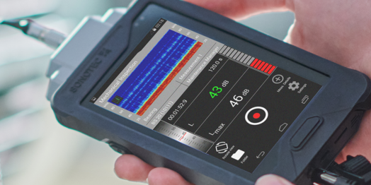
A digital ultrasonic flaw detector (e.g. SONOSCREEN ST10 or SONOWALL 70 with flaw detector upgrade) is required. The gage should be capable of transmitting and receiving ultrasonic pulses and displaying them in full-rectified form (A-Scan). Angle beam probes supporting automatic trigonometric calculations and DAC, DGS or AWS software are the absolute minimum for weld inspection. It is crucial that the device is calibrated and manufactured in accordance to the EN-12668-1 standard. In most branches, the equipment used for formal weld inspection must be calibrated against this standard at least once per year.
Ultrasonic probes: dual element straight beam probes (e.g. TS and TL series), angle beam probes (e.g. WS, WM and WL series) - The probe selection depends strongly on the material being inspected; its geometry, weld type, thickness, the minimum defect size to be detected and many other factors must be considered. To simplify the probe selection process, a general rule of thumb is to use 4MHz probes for a thickness range from 8-50mm and 2MHz for 50mm and above. For proper inspection, two angles must be used. For thinner welds up to 20mm, angles of 70° and 60° are recommended. For thicker objects, 45° and 60° are preferred.
Examination sketch
The next step is to draw the examination sketch. This should clearly display the probe movement zone, the part of the weld covered by the inspection, and the point where the ultrasonic beam is introduced to the part. On the tested object, the zero point of the measurement should be permanently set and marked on the sketch. It must be possible to exactly reproduce the test procedure based on the report made after test completion.
Couplant
Usually this is a water-based gel, oil, grease or wallpaper glue. It is very important that the same couplant is used throughout the whole testing procedure (i.e. calibration, estimation of transfer losses, sensitivity adjustment and testing).
Performing the Inspection
Surface preparation
First, a visual inspection of the weld and the surrounding material must be conducted, in order to determine if the surface is appropriate for ultrasonic testing. There may be weld spatters or other obstacles which could restrict probe movement; these should be removed prior to testing. Furthermore, the weld geometry should be inspected for possible root leakages or crown overlays as this will deliver geometry indications.
Equipment preparation
Before testing with angle beam probes, the beam index point and actual refracted angle has to be identified.
- The Beam Index Point is the point where the center of the beam exits the wedge of the probe. This point is a zero point for all trigonometric distance and depth measurements. It can be estimated using calibration block K1\V1.
- The verification of a probe-refracted angle is important for the correct distance and depth measurements and can also be performed with a K1\V1 block.
- The next step is to perform distance calibration. This procedure depends on the probe selection and can be done with a K1 or K2 block. In order to perform a proper calibration, the thickness of the block should be greater than the probe width. Distance calibration is required to obtain the precise speed of sound inside the material and the probe delay for accurate distance measurements. The preferred calibration type is a two-point calibration, where both of these factors are calculated at the same time.
- At the end, a test sensitivity adjustment has to be performed. This involves selecting the appropriate evaluation method and creating the evaluation curve on the device display. The DAC method requires a specially prepared calibration block of the same material, usually with side drilled holes at different depths (to achieve high accuracy, the depth of the holes should cover the range of actual testing). DGS and AWS do not require additional blocks because the curve computation is done empirically.
Testing the Weld
To cover 100% of the weld volume, the angle beam probe has to be moved back and forth perpendicular to the weld axis, preferably from both sides.
To ensure the detection of transverse discontinuities, it is recommended to move the probe back and forth at a 90° and 45° angle to the weld axis.
Classification of discontinuities: indications should be evaluated according to their envelope. First, the maximum amplitude due to the indication must be found. If the amplitude drops steadily to zero in all directions when the probe is moved away from the indication, this means that the discontinuity is smaller than the ultrasonic beam from the probe. If the amplitude does not drop to zero and remains within a -6dB dynamic range, it means that the indication is bigger than the probe beam size.
False indications occur frequently: these are due to mode converted waves, arising from the object geometry, and must be correctly evaluated and ignored. This is the most difficult part in the whole process of ultrasonic testing.
Acceptance criteria: These criteria are defined in the standard for each quality class. To illustrate this, let’s consider the following example on the left.
- As seen in the above graph, the acceptance level is equal to the reference level (DAC curve level) as long as the length of the indication is less than the material thickness. For indications which are longer than the material thickness, the acceptance level is 6dB below the reference level (equal to the registration level). This is because long defects are a bigger threat to any construction than point defects and must therefore be evaluated with a lower acceptance level.
- During inspection, those indications which are not accepted must be permanently marked.
- Before finishing and leaving the inspection site, couplant and other test residues have to be removed.
Do you have any questions?
Feel free to contact us! We will be happy to help you.